Ved at bekræfte knappen "Tillad alle cookies" tillader du brugen af cookies. Ved at klikke på knappen ”Konfigurer” kan du vælge hvilke cookies du ønsker at tillade. Du kan til hver en tid ændre eller ophæve din tilladelse i vores privatlivspolitik.
Solar power charging via floating enabling contact
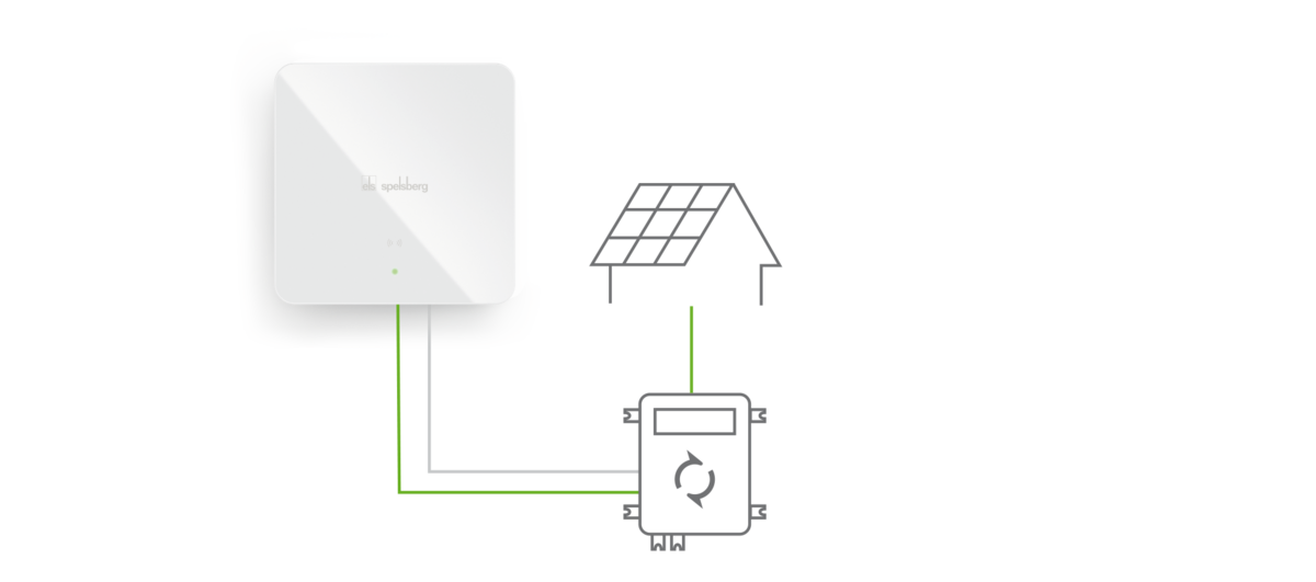
With solar power charging via an external enabling contact, the wallbox is connected via a control line with the inverter. The potential-free contact must be designed for a current of <25 mA. As soon as a previously defined PV excess (minimum charging power) is present, the an enabling signal sent by the inverter starts the electric vehicle charging process.
If a set threshold value is fallen below, charging stops since the enabling signal from the inverter is interrupted. Enabling control is performed by the inverter and in doing so this takes account of the conditions for switching on or off entered there.

Parameter configuration
Configuration of solar power charging via floating enabling contact (Smart Pro)
Before configuration in the Spelsberg Wallbox App can take place, the connection of a signal line to the floating contact of the PV inverter and the corresponding spring-cage clamps of the wallbox is necessary. You can find more information and instructions on this in the manual in Chapter 9.8 (Connection of the PV system signal line).
Once the connection via the signal line has been established, configuration via the Spelsberg Wallbox App can take place. Open "Advanced settings", display "Expert settings" and select "Dynamic load management (DLM)".
1. "Coordinator/charging point DLM role" parameter:
- Select "DLM coordinator".
2. "Sub-distribution current limit load management" parameter
- Enter here the maximum current per phase available to the wallbox and which may be limited by the distribution box. Max. 16 A per phase.
3. "Max. distributable charging current" parameter
- Enter here exactly the same value as for "Sub-distribution current limit load management", unless you wish to set the lowest charging current possible.
4. "DLM offset at PV input" parameter
- These parameters must be activated.
5. "Offset at external PV input (L1/L2/L3)" parameter
- Enter here the corresponding current offset per phase (1-A steps).
Note: The value for the current offset must be negative and will be deducted from the value of the operator sub-distribution current limit. Example: If the value of the "sub-distribution current limit load management" is 16 A and the "offset" is 6 A, when a signal is applied charging will be at a maximum of 10 A. If the result is a value of <6, then the charging process is paused.
6. "Logic behaviour of the external PV input" parameter
- Check that this parameter is set to "Active low".
Note: If the relay in the inverter closes when there is activity on the output, then in this use case the polarity should be set to "Active low". However, if the relay in the inverter opens when there is activity, then in this use case the polarity should be set to "Active high". This depends on the design of the inverter. The following is an overview of the behaviour of the system.
System output type | System output state | Polarity of input 1 | Behaviour |
|---|---|---|---|
| Normally Open | Off | Active High | Full charging current |
| On | Charging current reduced by current offset | ||
| Off | Active Low | Charging current reduced by current offset | |
| On | Full charging current | ||
| Normally Closed | Off | Active High | Charging current reduced by current offset |
| On | Full charging current | ||
| Off | Active Low | Full charging current | |
| On | Charging current reduced by current offset |
Note: A setting on the inverter must also be carried out for the solar power or current from which the enabling signal (High Level) should be sent via the floating contact to the wallbox, so that the wallbox starts the charging process. This is the threshold value that defines the conditions for switching on or off and should be set somewhat higher than the charging current set at the wallbox.
Case study:
The aim is that when there is sufficient solar power generated the wallbox starts the charging process or when there is insufficient solar power available stops it.
For this the inverter requires a potential-free output (relay with NO contact). This output is configured in the inverter such that it is open when there is to be no charging or closed immediately there is sufficient solar power available for charging. Both NO contacts of the potential-free output must be connected with terminal blocks PV1 and PV2 to the Spelsberg Wallbox. A 2-core wire with 0.5 mm² cores can be used for this.
In this example the sub-distribution has 16 A protection and the maximum charging current is also 16 A. Accordingly, for each phase 16 A must be entered for the "Sub-distribution current limit load management" and the "Max. distributable charging current". So that the charging process pauses if no signal from the inverter is present, the current offset must be the same as the "Sub-distribution current limit load management", i.e. -16 A, since 16 A - 16 A = 0 A. The logic behaviour is set to "Active low". In this example the following behaviour of the inverter applies: The relay in the inverter is open (Normally Open) in the quiescent state, so that if there is no signal (Off) the charging current is reduced by the current offset (16 A - 16 A = 0 A). If a signal is present (On), the contact closes and the charging process begins.
System output type | System output state | Polarity of input 1 | Behaviour |
|---|---|---|---|
| Normally Open | Off | Active Low | Charging current reduced by current offset |
| On | Full charging current |